(*Archived from adambaby.com 2012)
I recently* upgraded the LCD displays in my two CZ-101s to backlit versions. I was really tired of having to use a headlight just to program them in my dark studio. In doing so, I took the opportunity to overhaul one of them, which, since the day I had bought it some 17 years ago or more, had suffered from sticky keys and buttons, as though someone had spilt soft drink or similar poison into it.
Well, let me warn you, it was not an easy task. What follows are the notes and photos I made along the way to help me get the thing back together and working. I thought these may be of assistance to any future travellers down this path.
The difficulty in getting to the key-bed and switches is because they are sitting on circuit-boards that are three deep when accessed from the rear of the machine, and only the display board is connected by a plug and socket type ribbon. All the others are connected by semi-rigid soldered ribbons. This means that as you unscrew PCBs getting deeper into the synth, you have to juggle a bundle of boards. Finally, you have to lift them out as one, leaving just the rubber moulds (containing the carbon contacts that the switches and keys activate), the plastic switches, the keybed, and the chassis itself.
One trick that made it a bit easier was using hooks on suspension wires (attached to the ceiling above my work area) that allowed me to hold up the topmost boards while I got at the deeper ones.
Of course, alternatively you could just de-solder all those ribbon connectors - I weighed it up and thought this method was less trouble.
LCD DISPLAY
After you've removed the back cover (11 screws, 2 are in the battery compartment), you are facing two boards, MA1M and MA2M.


Above: MA1M
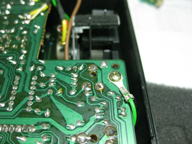
MA1M is held by 7 screws, one on the far right also holds down a lug from a green ground wire that connects multiple PCBs. Remove these, to be able to lift it up and unplug the 14 pin display connector from it's underside. Slip this and the 14 wires out from under the board. Remove the four short (5.5 mm) screws that hold the metal display mount. This bracket holds the display PCB in position against the viewing window. Now to get this out you'll probably need to also remove 2 of the screws holding the next-deeper PCB, to give some room for manoeuvering the mount.

Above: the display PCB mounted on it's metal bracket, behind MA3M, itself behind MA1M.


The stock display is a non-backlit Hitachi-HD44780-compatible 16x2 character LCD with drivers, on a PCB that is 84 x 44 mm. The front-back depth is 10 mm. Most back-lit replacements are closer to 13-14 mm, and often narrower than 44mm. How I got around both these problems was by mounting the new PCB along the crossbar of the bracket, instead of the arms.
The actual backlit display that I bought for $AUD 2.88 on ebay was 80 x 36 mm and had it's connectors at the top edge, not the bottom. This actually made it a bit easier to mount, but you have to remember to solder the wires so that they stick out upwards and not backwards from the display, to leave room for the battery compartment when you reassemble the chassis.
You will need to connect pin 1 (ground) to pin 16 (backlight cathode). Pin 2 (5 volts) to pin 15 (backlight anode) is connected via a current-limiting resistor, the exact rating will be given in the data sheet for the new display. After it's in, re-assemble the PCBs but don't close the unit up. Power up, and check the display appearance - you will almost certainly need to adjust the LCD contrast via the small trimpot accessed thru the rear of MA1M just near the display connector.


Above: the display I bought had different dimensions, and the connectors were along the top edge not the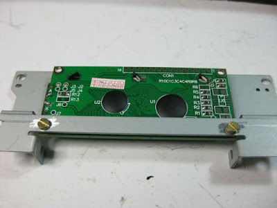
Above: new display in the mounting bracket, held at the bottom corners by the crossbar.


At the left side, unscrew the power switch PCB. This attaches to MA2M via a long 6-way ribbon. Now MA2M can be flipped up and over to lie against MA1M. You may want to use suspenders of some kind to hold these vertically while you access the deeper boards.


Now, as a bundle, all boards can be lifted up and out of the chassis. This will expose the soft rubber moulds that contain the carbon switch contacts (unless they are stuck to your PCB by gunk), which lie over the plastic buttons, and the keybed.

These rubber contacts are very delicate, lift them straight up gently and set them aside. The buttons will then just slide out of their tunnels. If you forget which ones go where, there are subtle little patterns inside the chassis that will give you a hint.


Text and photos copyright © Adam Inglis 2012


I recently* upgraded the LCD displays in my two CZ-101s to backlit versions. I was really tired of having to use a headlight just to program them in my dark studio. In doing so, I took the opportunity to overhaul one of them, which, since the day I had bought it some 17 years ago or more, had suffered from sticky keys and buttons, as though someone had spilt soft drink or similar poison into it.
Well, let me warn you, it was not an easy task. What follows are the notes and photos I made along the way to help me get the thing back together and working. I thought these may be of assistance to any future travellers down this path.
The difficulty in getting to the key-bed and switches is because they are sitting on circuit-boards that are three deep when accessed from the rear of the machine, and only the display board is connected by a plug and socket type ribbon. All the others are connected by semi-rigid soldered ribbons. This means that as you unscrew PCBs getting deeper into the synth, you have to juggle a bundle of boards. Finally, you have to lift them out as one, leaving just the rubber moulds (containing the carbon contacts that the switches and keys activate), the plastic switches, the keybed, and the chassis itself.
One trick that made it a bit easier was using hooks on suspension wires (attached to the ceiling above my work area) that allowed me to hold up the topmost boards while I got at the deeper ones.
Of course, alternatively you could just de-solder all those ribbon connectors - I weighed it up and thought this method was less trouble.
LCD DISPLAY
After you've removed the back cover (11 screws, 2 are in the battery compartment), you are facing two boards, MA1M and MA2M.

Above: MA1M
MA1M is held by 7 screws, one on the far right also holds down a lug from a green ground wire that connects multiple PCBs. Remove these, to be able to lift it up and unplug the 14 pin display connector from it's underside. Slip this and the 14 wires out from under the board. Remove the four short (5.5 mm) screws that hold the metal display mount. This bracket holds the display PCB in position against the viewing window. Now to get this out you'll probably need to also remove 2 of the screws holding the next-deeper PCB, to give some room for manoeuvering the mount.

Above: the display PCB mounted on it's metal bracket, behind MA3M, itself behind MA1M.


Above: lifting up the lower edge of MA1M, the display connector is seen. Note the trimpot just behind it, for the LCD contrast adjustment.


Above: take out a couple of screws from the intermediate board MA3M to remove the display.
The stock display is a non-backlit Hitachi-HD44780-compatible 16x2 character LCD with drivers, on a PCB that is 84 x 44 mm. The front-back depth is 10 mm. Most back-lit replacements are closer to 13-14 mm, and often narrower than 44mm. How I got around both these problems was by mounting the new PCB along the crossbar of the bracket, instead of the arms.
The actual backlit display that I bought for $AUD 2.88 on ebay was 80 x 36 mm and had it's connectors at the top edge, not the bottom. This actually made it a bit easier to mount, but you have to remember to solder the wires so that they stick out upwards and not backwards from the display, to leave room for the battery compartment when you reassemble the chassis.
You will need to connect pin 1 (ground) to pin 16 (backlight cathode). Pin 2 (5 volts) to pin 15 (backlight anode) is connected via a current-limiting resistor, the exact rating will be given in the data sheet for the new display. After it's in, re-assemble the PCBs but don't close the unit up. Power up, and check the display appearance - you will almost certainly need to adjust the LCD contrast via the small trimpot accessed thru the rear of MA1M just near the display connector.

Above: original display, held at the top corners, connectors at the bottom.

Above: the display I bought had different dimensions, and the connectors were along the top edge not the
bottom.

Above: new display in the mounting bracket, held at the bottom corners by the crossbar.

Above: make sure whatever display you use, that it lines up with the viewing window.

New display in place.

GOING DEEPER
To get deeper into the machine, say, to clean the keybed, you need to desolder the battery connectors, and the green ground wire from MA2M. While you're there, de-solder the grey 2-core connecting wire from MA2M.
De-solder the multi-core wires from the right edge of MA1M that connect to the pitch wheel and the volume pot.
Work MA1M up and out carefully - you'll find the midi connectors make it a a bit tricky to free due to the plastic lugs underneath.
Free the cartridge connector by removing 3 screws.

MA2M


Above: MA1M suspended by hooks and wires to allow access to deeper PCBs


At the left side, unscrew the power switch PCB. This attaches to MA2M via a long 6-way ribbon. Now MA2M can be flipped up and over to lie against MA1M. You may want to use suspenders of some kind to hold these vertically while you access the deeper boards.

Above: the intermediate board with foil removed, the key switch board with foil.

MA3M is the intermediate board under MA1M, covered by a foil card. Remove the 4 screws (one thru a ground wire lug).
At this point you can also expose the long piano-key-contact PCB and it's foil cover by removing the 12 x 7.5 mm screws along it's length (the screws visible through the circular cut-outs can be left til just before you need to actually remove the individual piano keys), not forgetting which one has a ground lug attached.
Carefully moving this bundle of boards forward and back will give you access to the deepest PCBs that have the mounted LEDs and the switch contacts, CN1M on the right, and CN2M on the left. The former is held by 7 screws (2 through a plain cardboard shield) and the latter by 12 screws (7 through a foil shield, 1 of these attaches a ground lug). The small "Master Tune" PCB, CN4 can remain attached to CN2M via it's short ribbon, if you unscrew it from the chassis.
Carefully moving this bundle of boards forward and back will give you access to the deepest PCBs that have the mounted LEDs and the switch contacts, CN1M on the right, and CN2M on the left. The former is held by 7 screws (2 through a plain cardboard shield) and the latter by 12 screws (7 through a foil shield, 1 of these attaches a ground lug). The small "Master Tune" PCB, CN4 can remain attached to CN2M via it's short ribbon, if you unscrew it from the chassis.


Now, as a bundle, all boards can be lifted up and out of the chassis. This will expose the soft rubber moulds that contain the carbon switch contacts (unless they are stuck to your PCB by gunk), which lie over the plastic buttons, and the keybed.

These rubber contacts are very delicate, lift them straight up gently and set them aside. The buttons will then just slide out of their tunnels. If you forget which ones go where, there are subtle little patterns inside the chassis that will give you a hint.

There are two long metal brackets held by 9 x 5.5. mm screws that hold the piano keys in place. These have a rubber strip along the top edge.
Having been burnt before by synths with fussy piano-keys, I made careful note of the markings of each key as I removed it. The black keys seem to be all the same. The white keys are, from left to right:
S1 B5 A1 G2 F2 E5 D4 C7 B4 A1 G2 F2 E6 D7 C6 B3 A1 G2 F2 E7 under the long bracket.
D6 C5 B8 A1 G2 F2 E8 D5 C4 under the short bracket.
Note there is a gap between the contact for the first key, S1, and the next in line, that has a slightly different corresponding rubber mould.
Now the plastic chassis and keys should be ready for a good clean!

The technical term is Gunk.


Above: chassis cleaned, keys, buttons and rubber switch pads in place


Text and photos copyright © Adam Inglis 2012


Comments
Post a Comment